5. Getting Started
5.1 License Activation
When you first start HARP, you will notice that only limited functionality is available on each page. To activate your license:
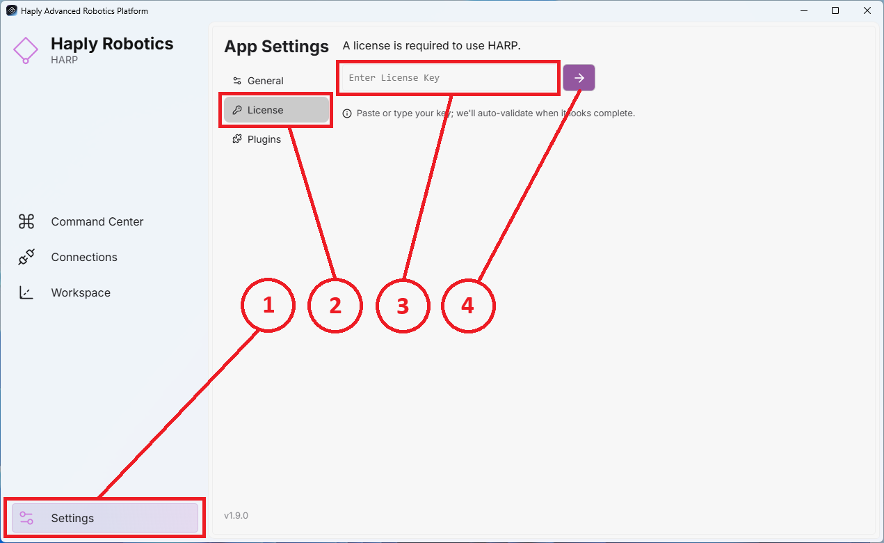
- Locate the Settings icon on the left side panel and click it to open the Settings page.
- In the top-right area of the Settings page, enter your license key in the designated text field.
- Input the License Key.
- Click the Activate License Button to complete activation.
- Once the license is successfully activated, a new button labeled Revoke License will appear.
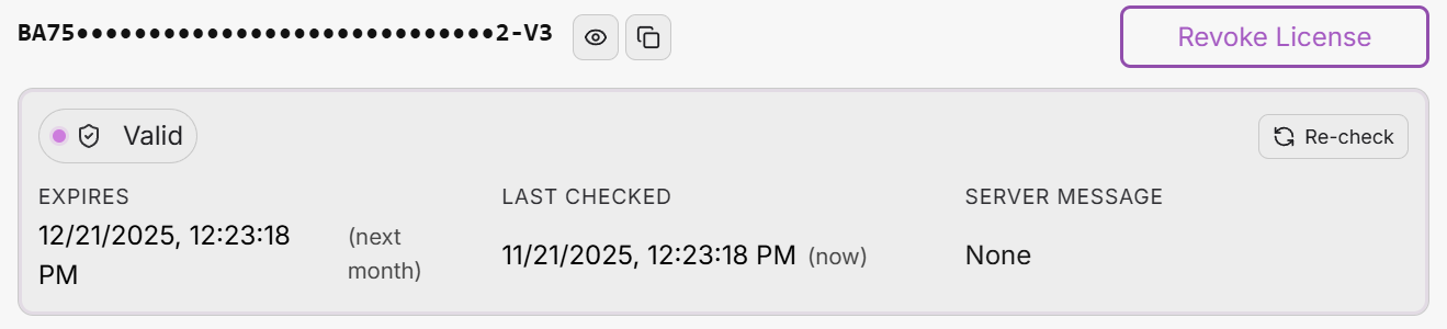
To activate an internet connection is required.
Unless negotiated in the purchase of your license (for security specific applications) HARP always requires an internet connection on launch
5.1.2 License Release
To release a license for use on another machine, click the Revoke License button.
5.2 Create a Project
To create a project, navigate to the Connection screen.
- When HARP launches, it will navigate to the Connection Screen and attempt to load your most recent project automatically
- If no previous project is found, HARP will present you with the Create or Open project buttons.
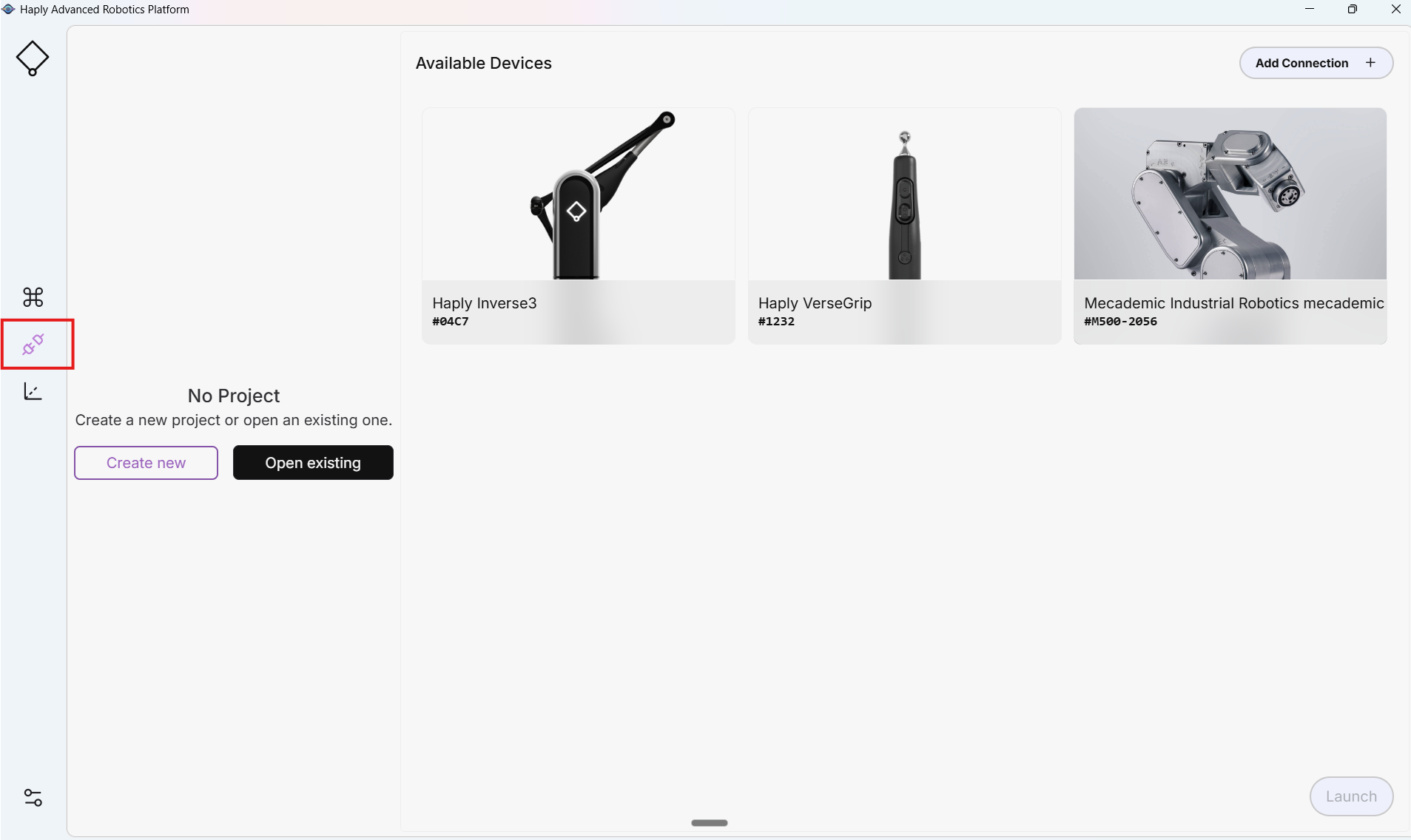
You have two options:
- Create New: Enter your project name and choose a directory where your new project folder will be created.
example:
Your Project name: MyFirstProject
Chosen Directory: My Documents
A folder is created at “My Documents/MyFirstProject/” with all the project files inside. - Open Existing: Select an existing project file to continue work.
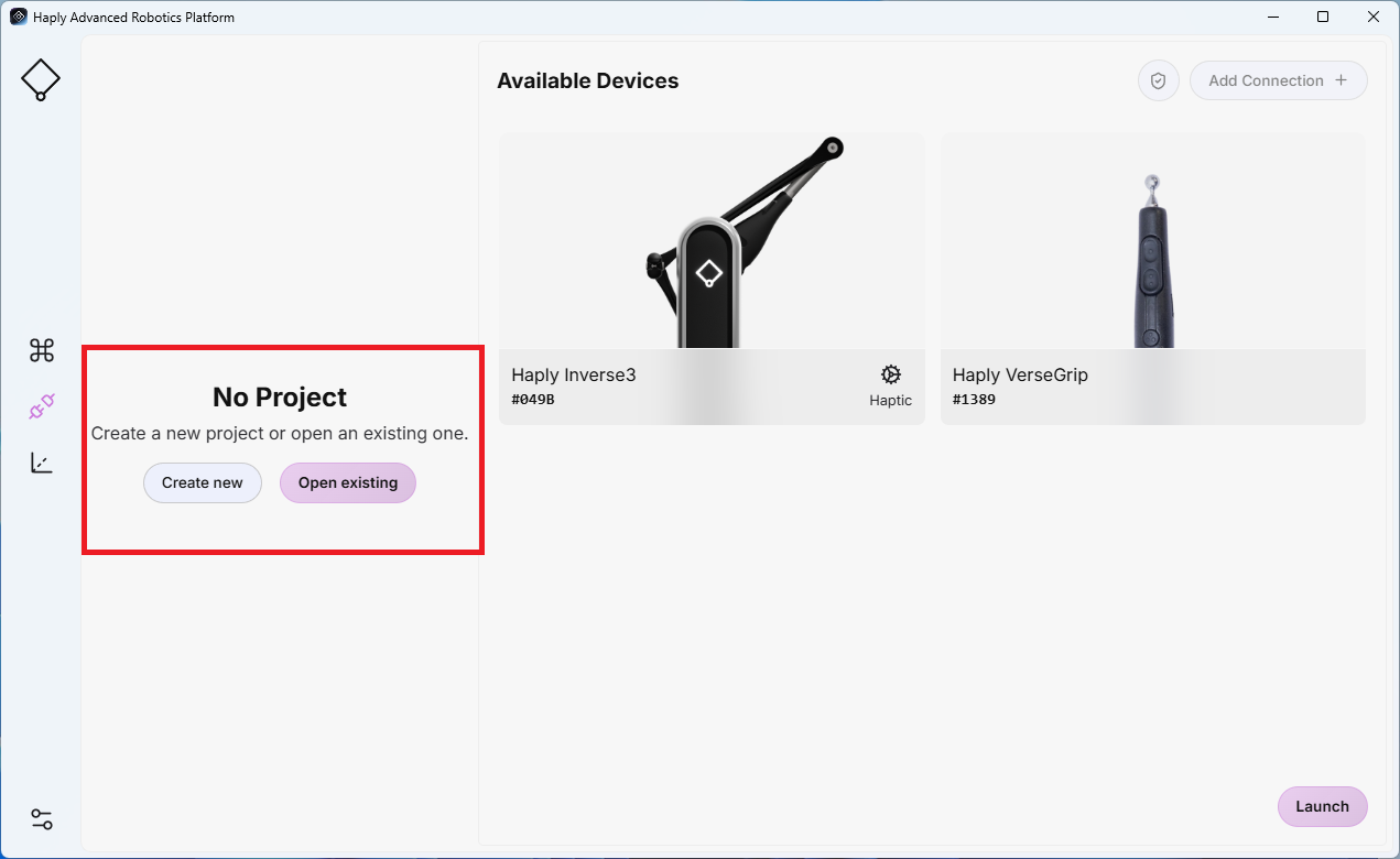
Each project includes a project file called Project.json. This file defines the configuration and structure of the project.
After using either Create New or Open Existing, You are ready to start connecting devices.
5.3 Connect Devices
While wiring is unique to each system, Appendix A includes some wiring diagrams for common configurations.
After connecting a new device, verify correct motion direction and speed at low speed with the cell clear of people and equipment
5.3.1 Connections Screen
- The Connections screen updates to show any Haply devices currently connected, as well as devices previously saved to the open project.
- Devices can be connected over COM ports or IP (see 4.3 Connections for network guidance).
- All connected devices must be calibrated prior to operation. Calibration procedures are detailed in Appendix C and should be followed during initial setup.
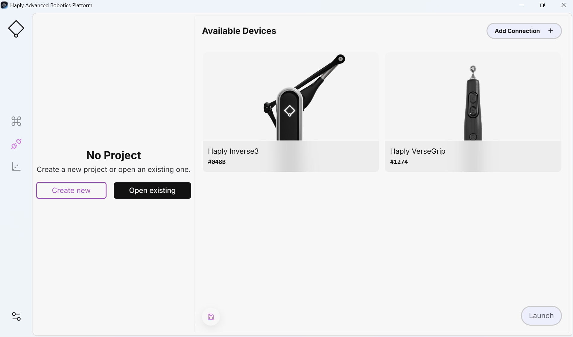
5.3.2 Add a Follower
- Create or Open a project before adding a Follower
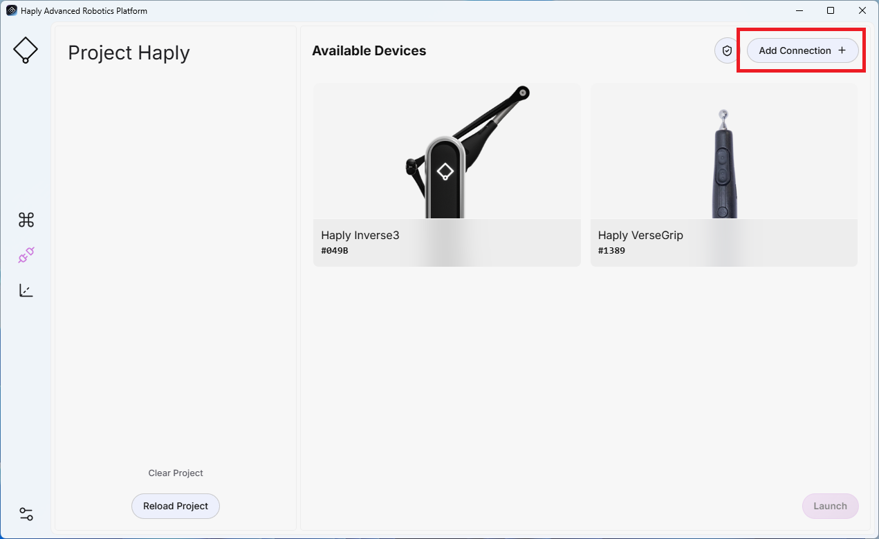
- Click Add Connection at the top of the screen.
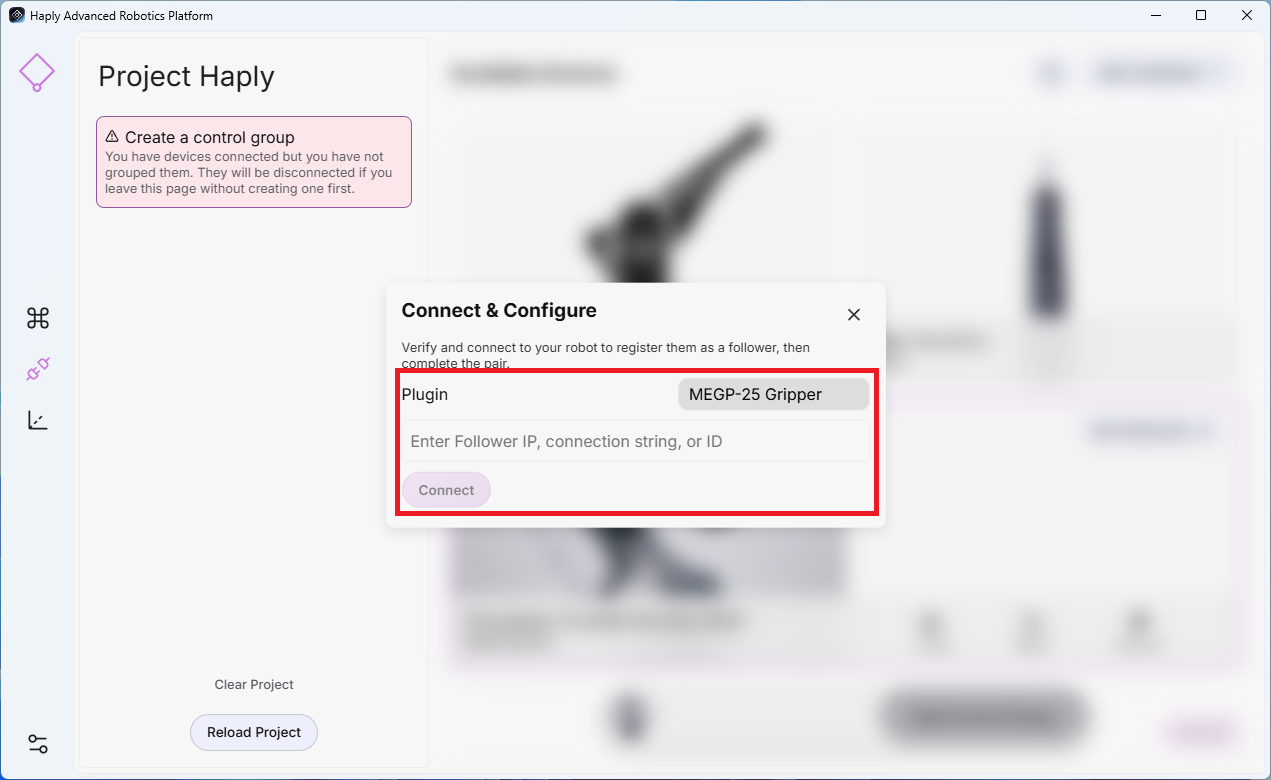
- Choose the correct Plugin for your Robot Arm and enter its IP, Connection String or ID.
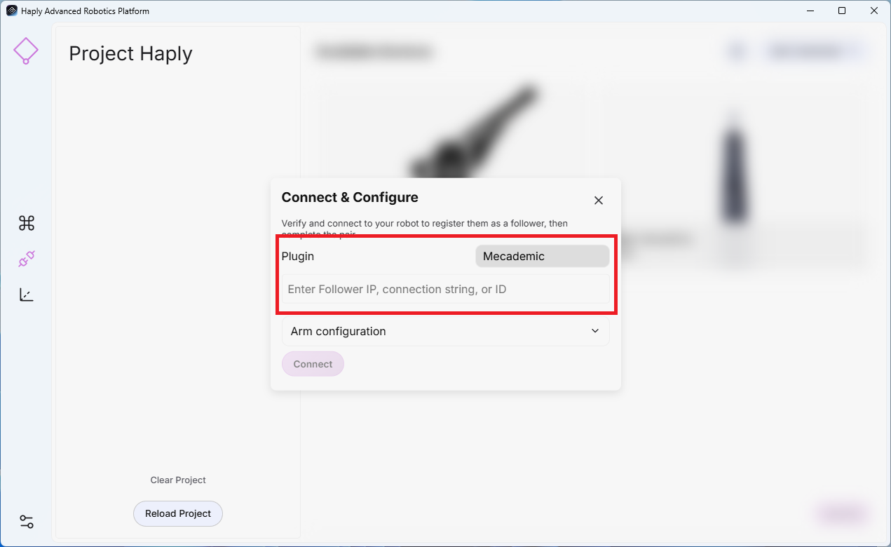
- Arm Configuration (optional):
- Orientation (Degrees) ( X, Y, Z)
- Position Offsets (meters) for any undefined moves (X, Y, Z)
- Velocity Limits for safe default motions. (%)
- Allowed to move: Enable only if it is safe for the arm to move immediately when HARP starts.
- Click Connect.
5.3.3 Add an End-Effector
End-Effectors are dependent on the parent follower. You will add the end-effector connection once your follower is connected.
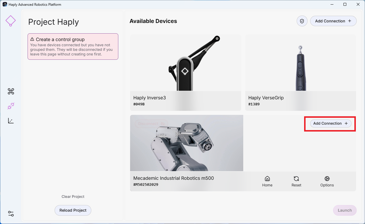
- After adding your robot connection, select Add Connection in the Parent robot where the end-effector is connected.
- Select Plugin: Choose the plugin named for your gripper.
- Address: Enter the device’s IP address or COM port (e.g., COM11).
- Click Connect.
5.3.4 Create a Control Group
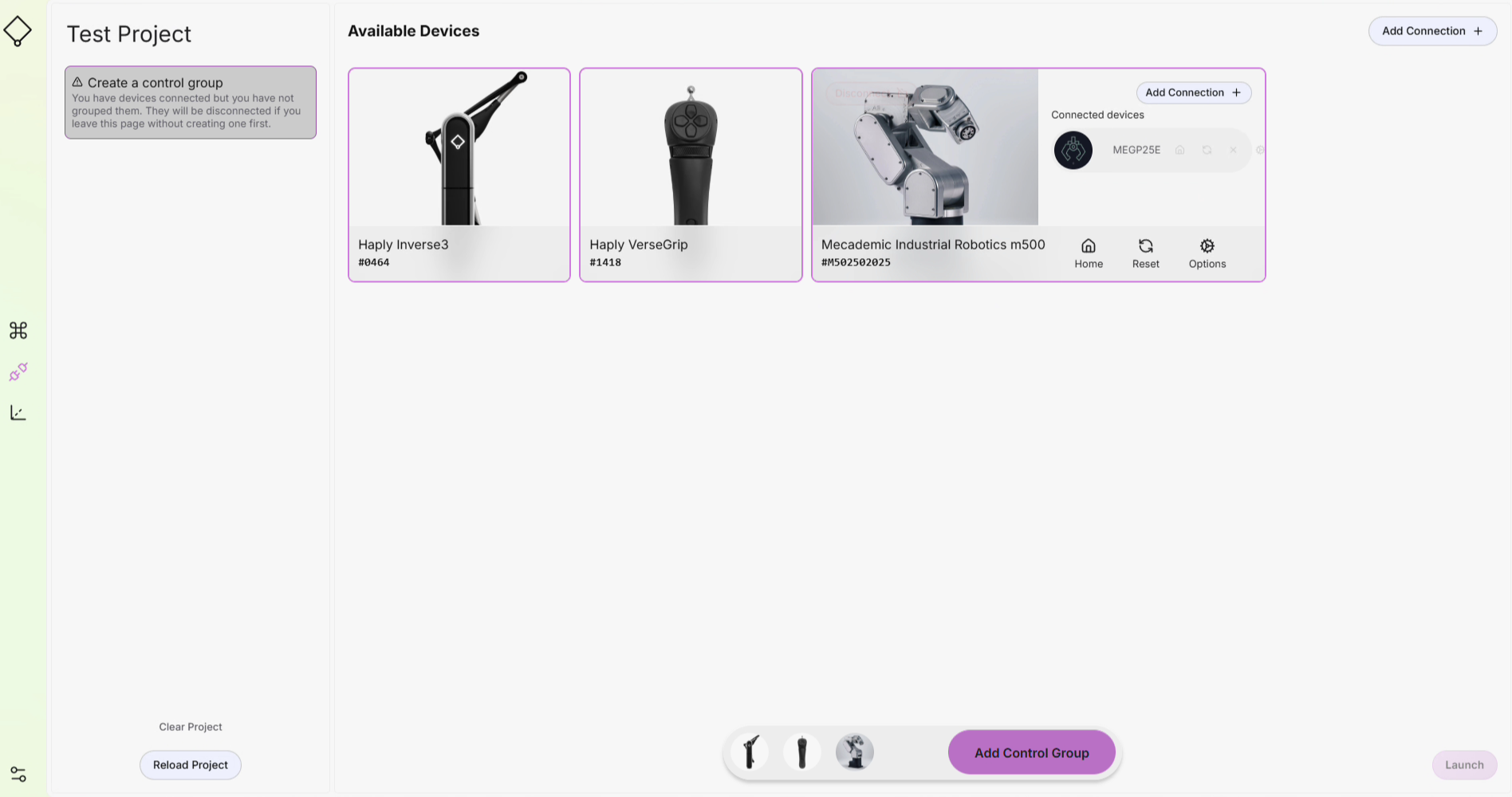
- The name of your project
- In the Connections screen, select each device you want in your Control Group.
- Click Add Control Group at the bottom.
- The control group appears on the left and is saved to your project.
5.3.5 Launch Teleoperation
- When your control group is configured and connected, click Launch (bottom‑right) to begin teleoperation.
5.3.6 Saving your project
The current state of your project will be saved in any of the following actions
- Press the Launch button in the Connections Screen
- Press the save button in the workspace configuration screen
- Create a Macro
- Close the application
5.3.7 Load a Project with different set of devices
When you load a project that has been created with a different robot, HARP updates the control group automatically as long as the same type of device is connected .
5.4 Workspace Configuration
The workspace configuration page allows setup and configuration of the objects in your workspace.
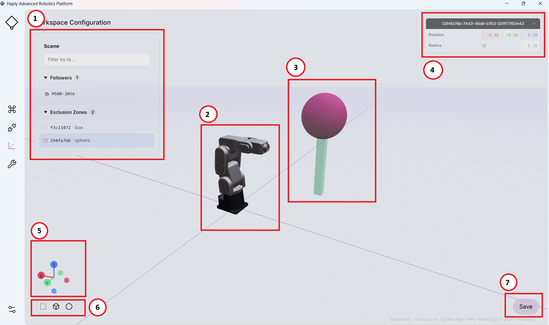
| 1 | Items List | A list of Followers, limits and exclusion zones in the workspace | |
|---|---|---|---|
| 2 | Follower - Robot | Move, rotate, flip your Robot arm to be located in your workspace as it is in the real world system. Set robot limits in XYZ to define areas the robot should avoid. Provides Haptic feedback to the user when they are against a virtual limit | |
| 3 | Exclusion Zones | Set the position and size of virtual shapes to prevent the robot end-effector from entering the volume of the shape | |
| 4 | Selected Item Settings | A menu providing all variables needed to adjust the set point for your currently selected item from the (1) Items List | |
| 5 | Workspace Reference Frame | Right-hand reference frame to define the objects in scene | |
| 6 | Add Exclusion Zone | Show robot limits, Add a cube or add a sphere symbols, respectively, allow you to interact with the workspace and set it up for your system. | |
| 7 | Save Workspace | Save changes to your project files - This tool does NOT use auto-save - remember to save your changes (To save all your changes follow the procedure on saving a project 5.3.6 Saving your project). |
Incorrect workspace limits or exclusion zones can cause the robot to move into hazardous areas. All limits and zones shall be validated physically at reduced speed or reduced scaling before operation around people or equipment.
5.4.1 Robot Workspace
On the Workspace configuration screen (top‑left), you’ll see a list of objects in your workspace. Selecting the Robot Arm reveals editable fields on the right that let you:
- Move the robot in the workspace – adjust the arm’s base position within the scene.
- Rotate the robot in the workspace – set the arm’s base orientation.
- Define workspace limits – specify the boundaries the robot is permitted to move within.
- Haptics: Enable / Disable haptics when the robot reaches a robot limit
Make incremental changes and verify clearances in the 3D view before applying larger moves.
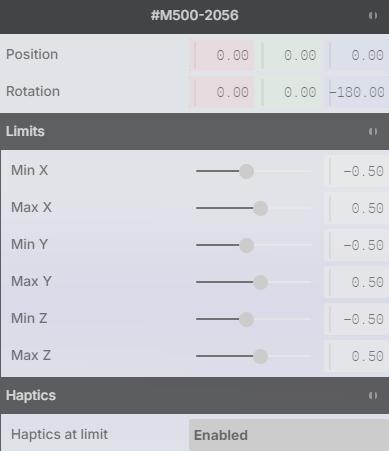 | |
| Position: X, Y, Z (meters) | |
| Rotation: X, Y, Z (degrees) | |
| Limits: (meters) Min X, Max X Min Y, Max Y Min Z, Max Z |
5.4.2 Robot Limits
Workspace limits define the limits that the robot can operate in. The robot arm will be prevented from moving past the set distances from the robots base reference frame. These limits also provide a haptic barrier that your Haply input device allows you to feel during operation and the physical boundary the robot itself cannot exceed.
- When you click Save (bottom‑right), HARP stores these limits in the project and sends the same limits to the robot controller base.
- This dual‑layer approach provides redundancy: even if the application were to fail, the controller‑side limits continue to enforce a safe boundary.
The on‑robot workspace limits are set approximately 1 cm outside the virtual limits to avoid false collisions and ensure smooth haptic rendering. This offset may vary between versions and brands.
5.4.3 Virtual Objects
On the Workspace Configuration screen, the Object Palette (bottom‑left) provides two primitives: a Cube and a Sphere. Click either icon to add that shape to your workspace.
**TODO Image missing get new screenshot **
- After adding an object, it appears in the Objects list (top‑left).
- Selecting an object reveals its Properties panel on the right.
In the Properties panel you can define:
-
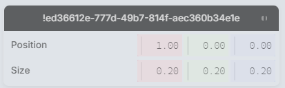
Location/Position (X, Y, Z) – place the object precisely in the workspace. (by default the origin of either object is located at the center point of the object)**
-
Size/Scale – adjust the object’s dimensions.**
- Cube/Box: set Width, Depth, and Height. For example, to create a tall, narrow rectangle, first place a cube where you want it and then increase Height while reducing Width and/or Depth.
- Sphere: set Radius (or uniform scale) to reach the desired size.
** Units are defined in meters
Position the object first, then refine its dimensions for easier alignment with nearby elements
5.5 Robot Options - Mecademic
HARP is designed as a modular control platform, enabling integration with a variety of robot arms through manufacturer-provided robot modules. Each robot model has unique kinematic parameters, motion limits, tool definitions, and safety configurations, all tuning and calibration parameters must be defined by the robot manufacturer. HARP does not provide robot-specific tuning settings.
5.5.1 Default Robot Module
The HARP software includes the module for the MECA500 robot arm. This module has been developed based on the manufacturer’s publicly available specifications and is intended to provide an out-of-the-box experience for users of the MECA500 robot.
5.5.2 Robot Settings
The following parameters described below are taken from official Mecademic documentation. For more in depth details check Mecademic’s Official Resources.
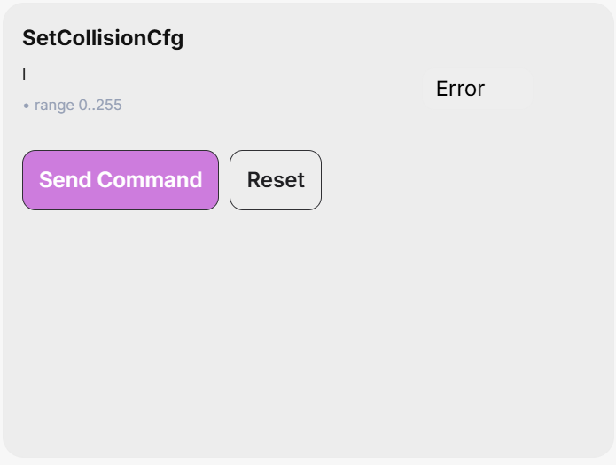
SetCollisionCfg
This command specifies the event severity for the collision supervision (robot links, tool sphere, and MPM500 module).
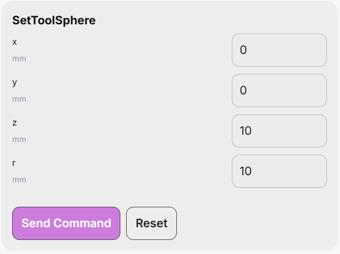
SetToolSphere
This command defines a sphere fixed in the flange reference frame (FRF). Interferences between that sphere and the robot links as well as the outside of a bounding box set with the SetWorkZoneLimits command can then be supervised, as defined by the SetWorkZoneCfg and SetCollisionCfg commands.
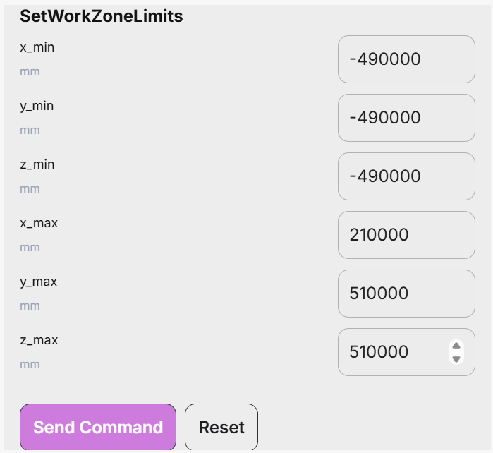
SetWorkZoneLimits
This command defines a bounding box (a cuboid), the sides of which are parallel to the axes of the base reference frame (BRF). The arguments of the command are the coordinates of two diagonally opposite corners, referred to as “minimum” and “maximum” corners, such that each coordinate of the minimum corner is smaller than the corresponding coordinate of the maximum corner.
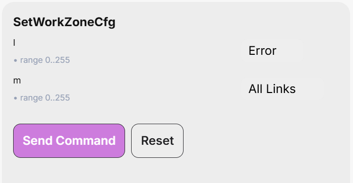
SetWorkZoneCfg
This command specifies the “event severity” for the work zone limits supervision and the robot parts that need to be verified.
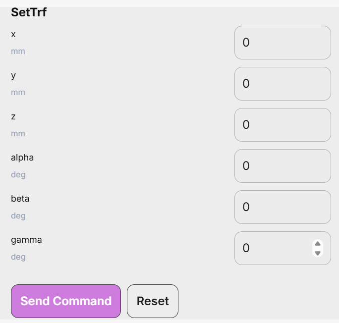
SetTrf
This command defines the pose of the TRF with respect to the FRF. Note that this command makes the robot come to a complete stop, even if blending is enabled.
SetAutoConf
This command enables or disables the automatic posture configuration selection, to be observed in the MovePose and MoveLin* commands. This automatic selection, in conjunction with the turn configuration selection, allows the controller to choose the “closest” joint set corresponding to the target pose.
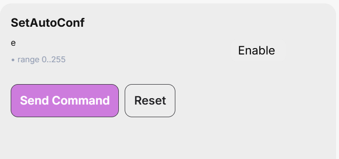
In the case of MoveLin* commands, enabling the automatic posture configuration selection allows the change of configuration, but only if the path happens to pass exactly through a wrist or shoulder singularity.
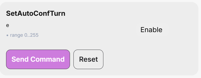
SetAutoConfTurn
This command enables/disables the automatic turn selection for the last joint of the robot. It affects the MovePose command and all MoveLin* commands. When the automatic turn selection is enabled, and a MovePose command is executed, the last joint will always take the shortest path, and rotate no more than 180°. In the case of a MoveLin* command, however, enabling the automatic turn selection simply allows the change of turn configuration along the linear move.
5.6 Settings
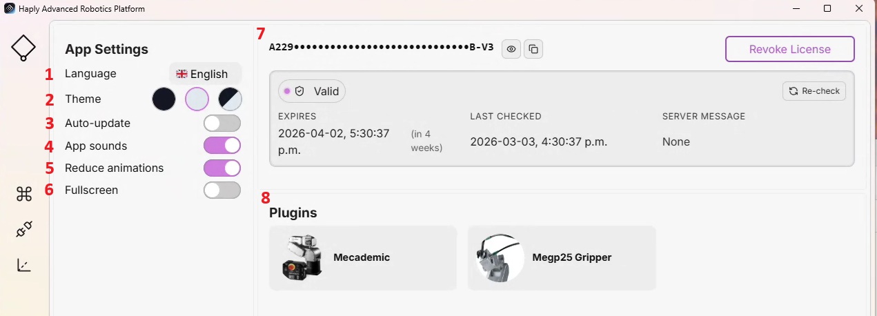
| 1 | Language | Choose the application UI language. | Dropdown of available languages |
|---|---|---|---|
| 2 | Theme | Select Appearance | Light, Dark, System |
| 3 | Auto-update** | If enabled, HARP checks for updates when the application launches. **Currently not a built in feature** | Toggle |
| 4 | App sounds | Enable or disable interface sound effects. | Toggle |
| 5 | Reduce Animations | Prevents the left toolbar from extending on hover. | Toggle |
| 6 | Fullscreen | Provides a fullscreen UI for Proper HMI usage | Toggle |
| 7 | License | Enter a license key, manage activation status | Input field + Activate / Revoke buttons |
| 8 | Plugins | Installed Robot and End-Effector module list |