SICK Safety Controller
FlexiSoft Safety Controller
Safety controllers are commonly used in industrial automation to help manage interactions between machinery, equipment, and personnel.
This section describes the integration of the SICK FlexiSoft safety controller with HARP. When connected, the safety controller can monitor external safety devices and communicate its current safety state to HARP in real time.
This allows HARP to respond appropriately to safety-related conditions, such as pause or stop requests, based on the signals received from the safety controller.
Terminology
-
PLC — Programmable Logic Controller: A controller used to execute automation and control logic.
-
IP Address (
connect_addr): The static IP address assigned to the safety controller or communication gateway. A static IP address is required to maintain a consistent connection with HARP. Avoid using DHCP, as the assigned IP address may change after a power cycle. -
Default Gateway (
gateway): The gateway address used by the local network. Common examples include192.168.0.1and10.0.0.1, depending on the network configuration. -
STOP Byte (
estop_byte): The configured byte used by HARP to monitor a full-stop or emergency-stop condition. -
PAUSE Byte (
pause_byte): The configured byte used by HARP to monitor a temporary process interruption. When triggered, HARP pauses teleoperation in a manner similar to releasing the clutch on the leader device.
Download - Safety Designer
SICK provides Safety Designer, a software application used to configure and program supported SICK safety controllers.
Safety Designer provides a graphical interface for:
- Creating and routing safety logic
- Verifying and signing safety programs
- Monitoring and debugging the safety configuration
- Configuring communication with the safety controller
- Transferring safety programs to the controller
For detailed instructions on installing and using Safety Designer, refer to the official SICK documentation and support resources.
Example Hardware
The hardware required for this example setup:
- FlexiSoft CPU - FX3-CPU000000
- FLexiSoft System Plug - FX3-MPL000001
- FlexiSoft Programming Cable - DSL-8U04G02M025KM1
- FlexiSoft Ethernet/IP module - FX0-GENT00000
- FlexiSoft XTIO - FX3-XTIO84002
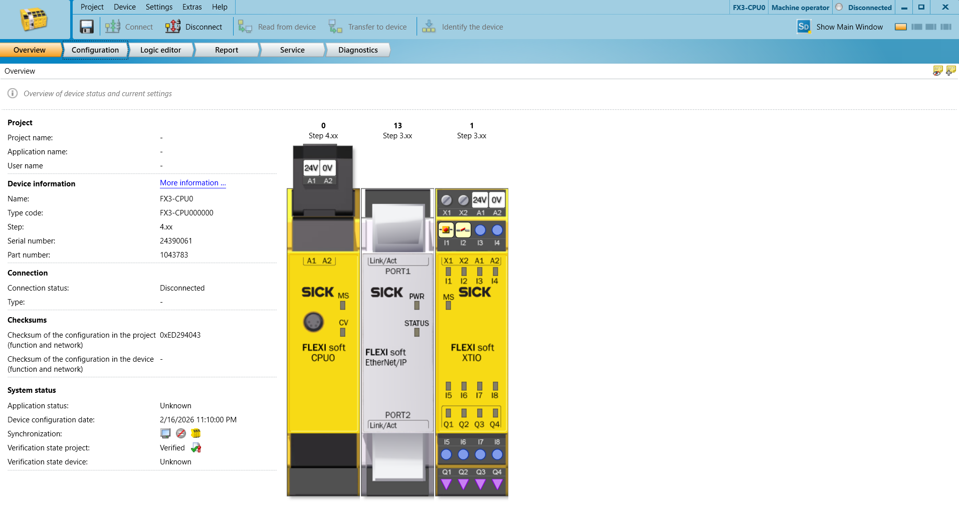
Setup your Safety PLC
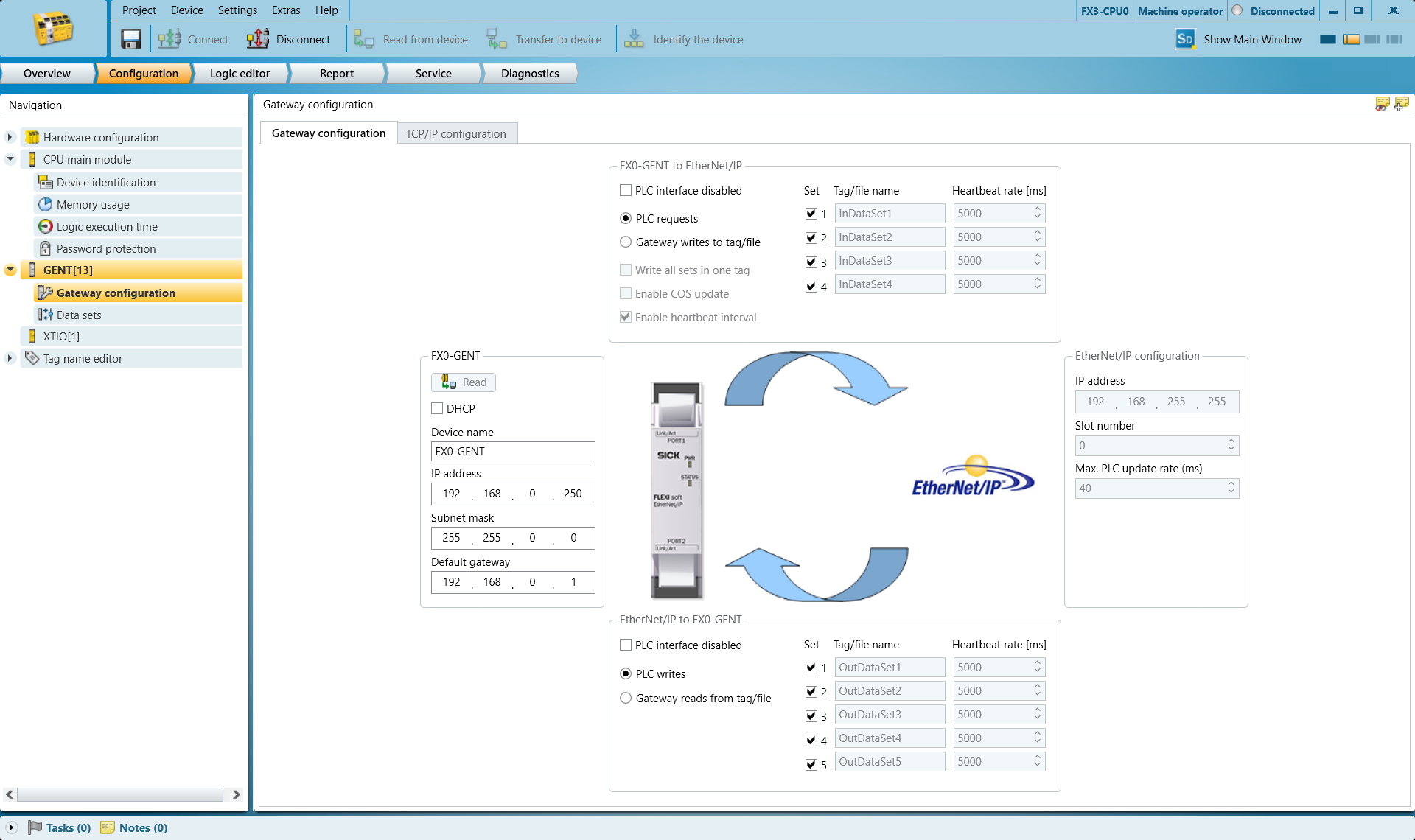
Network Setup:
In the GENT gateway configuration tab setup your Ip address and Default gateway
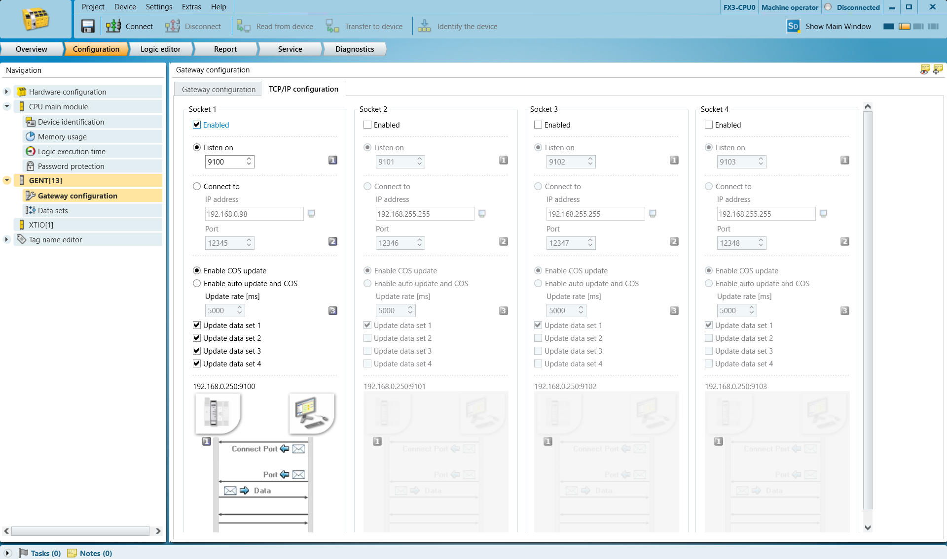
Go to the TCP/IP Configuration tab and enable Listen On and set your preferred port number. The default, 9100 is fine in most cases.
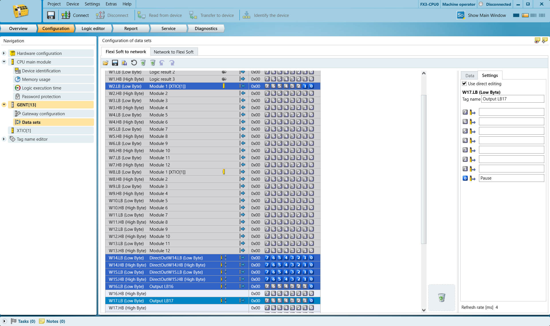
Go to Data sets and decide which output bytes you want to use for triggering STOP and PAUSE
Harp monitors Bit 0 of whichever byte you choose. It treats the Byte like a Boolean. Do not pick other bits, they will not work.
Here we use:
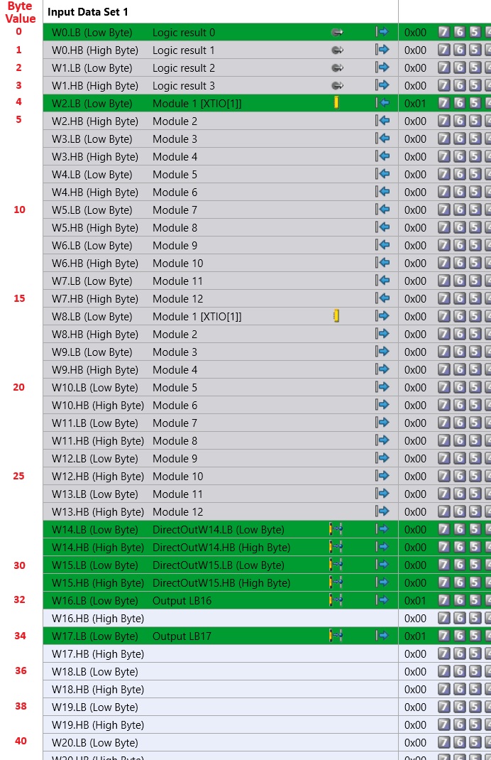
Byte 16 (Low Byte) for STOP
Byte 17 (Low Byte) for PAUSE
Select Line W16.LB (low byte) and notice on the right side at bit 0, you can name it STOP
This tagging is to help identify the items in your program later.
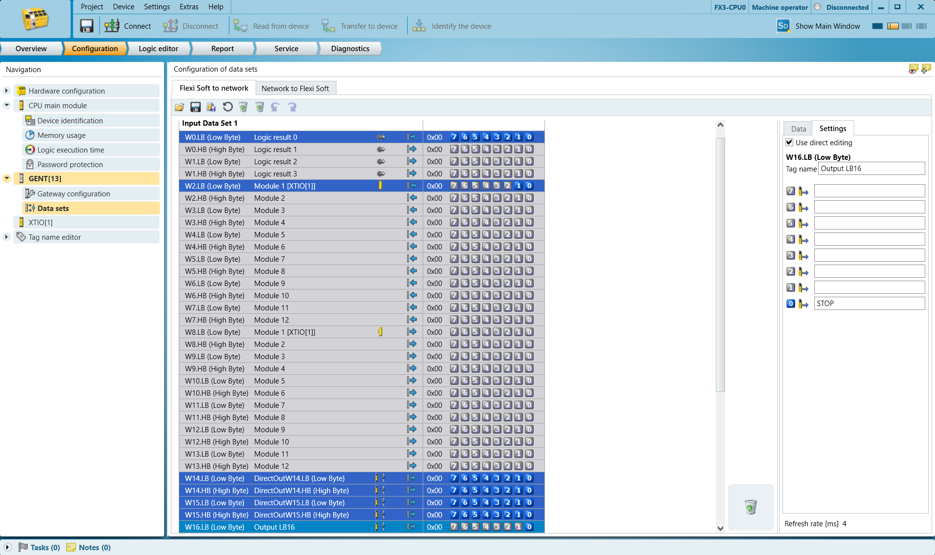
Select line W17.LB (low byte) and notice on the right side at bit 0, you can name it PAUSE
Programming
HARP expects the configured STOP and PAUSE bytes to be HIGH when the system is in its normal ready state.
This monitoring logic allows HARP to confirm that the safety controller is connected and reporting a valid operating state before robot operation begins. If communication with the safety controller is lost, HARP treats the monitored safety signals as unavailable and prevents operation until communication is restored and the configured bytes return to the expected HIGH state.
The example below uses:
- A normally open (N.O.) push button to represent a device such as a door switch or light curtain. This input is connected to the PAUSE signal at
17.LB. - A normally closed (N.C.) emergency-stop contact connected to the STOP signal at
16.LB.
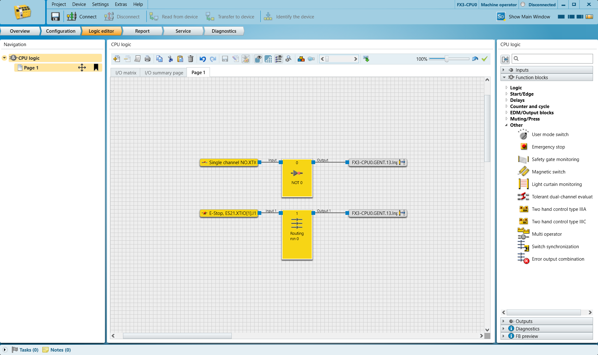
If the N.O. input is triggered, HARP pauses teleoperation until the input is released and the PAUSE signal at 17.LB returns to the expected HIGH state.
If the E-Stop is triggered, HARP stops the active session and prevents operation from continuing. Once the E-Stop condition has been cleared, the system must be reset before operation can resume.
Modify the PLC logic to match the requirements of your application and safety architecture. Multiple safety devices can be combined into a single monitored tag if required.
The PLC logic should also be integrated appropriately with the robot manufacturer's built-in safety functions.
Once the safety program has been configured and validated, transfer it to the PLC using the Transfer to Device button, then continue to the next step.
Map the bytes you chose and the Byte Value it corresponds to in this chart below.
HARP Project Setup
- In an existing HARP project, Navigate to the Connection Screen and click the Shield icon beside the Add Connection button
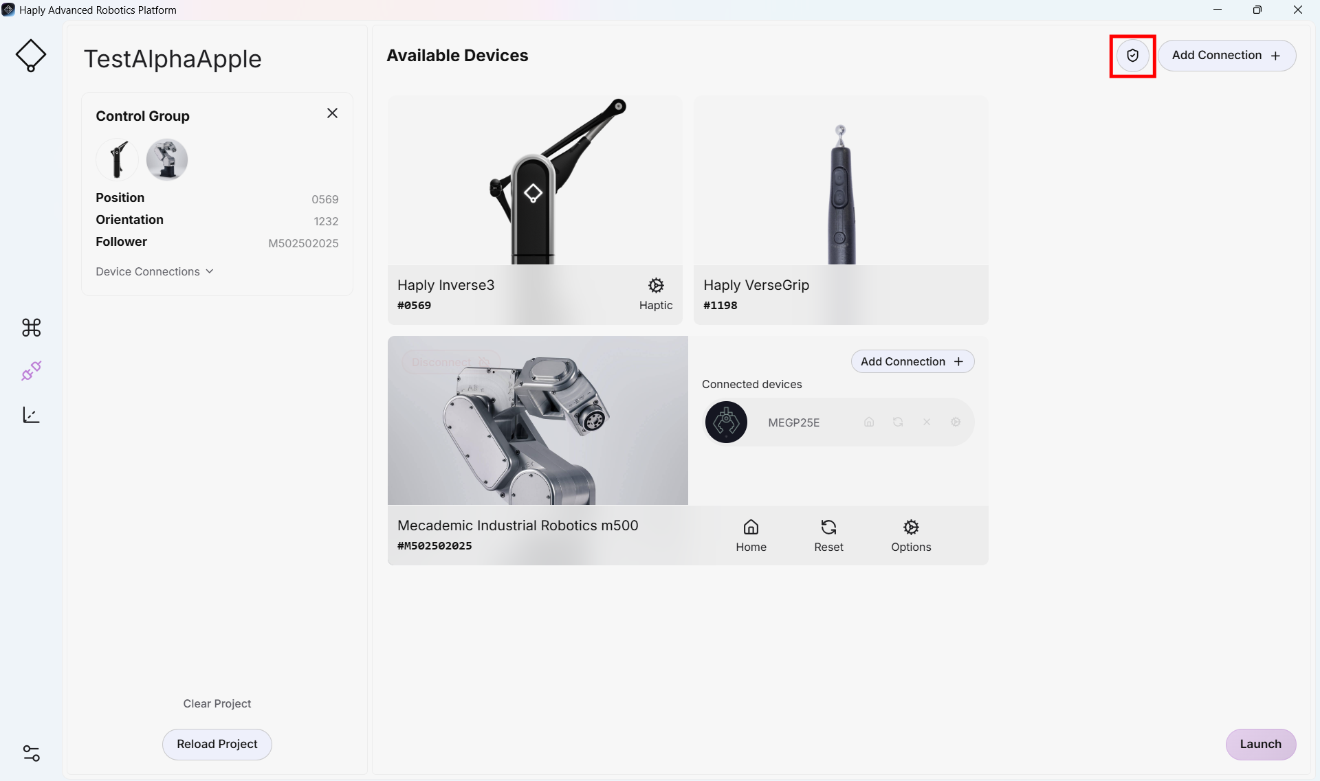
- Enable the Safety Controller toggle
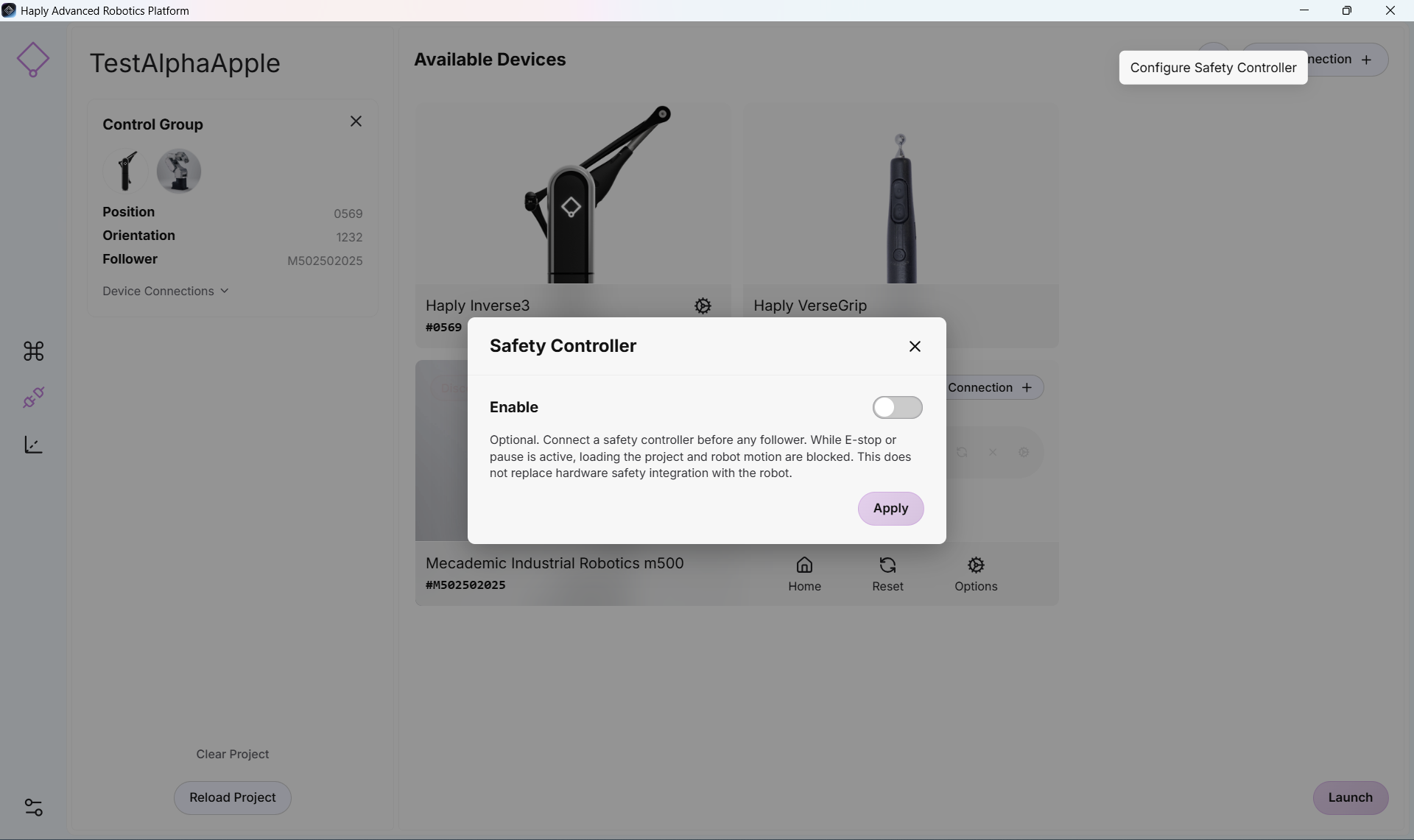
- You now have access to the configuration settings of your safety controller
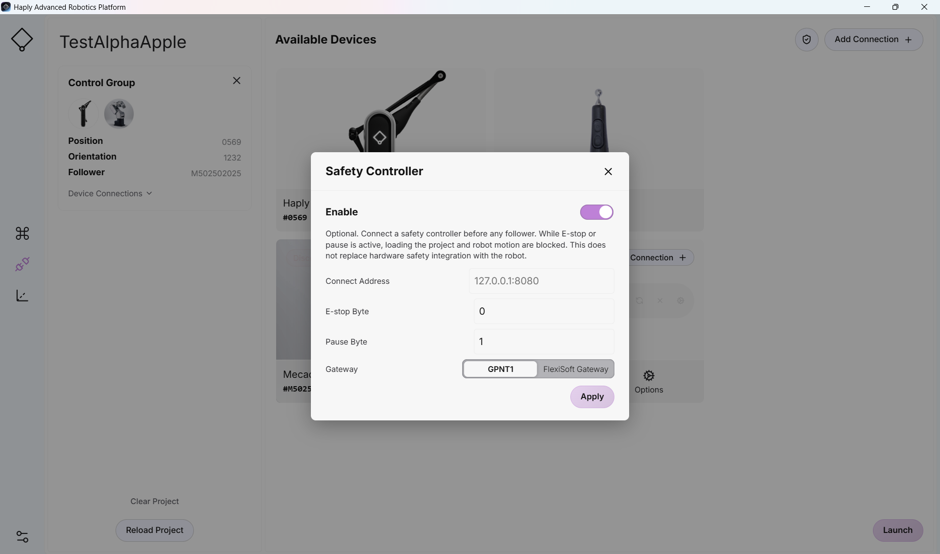
-
Take the IP address and byte numbers selected above. Apply them to the settings in the fields of the form
If you are using a FlexiSoft controller - select FlexiSoft toggle. GPNT is used for Flexi-Compact
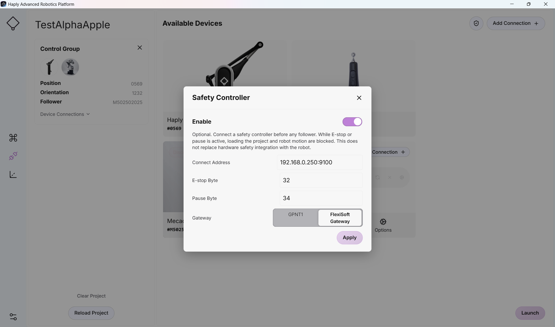
- If all connections have been done correctly, you'll be able to use the Control screen with no issue.
If you cannot move past the connection screen, or the control screen wont' allow robot motion. Ensure you don't have any Emergency devices triggering the outputs. Ensure the connection to the device is wired, powered on and look functional on the front panel.